WSPR transmitter shows true value of Raspberry Pi for hacking

wspr

Don’t get us wrong, we love our Raspberry Pi. But if you’re merely running a Linux image without adding a hardware hack into the mix you’re missing out on part of the power for which the platform was developed. This project is a great example of how to embrace the Raspberry Pi’s ability to deliver both low-level hardware access, and solid embedded Linux performance. [Dan Ankers] and [Threeme3] have developed a program which turns the RPi in to a WSPR transmitter. The GitHub readme shares many of the details on how it was done. But you’ll also want to dig through the .c file to see how they’re making use of the GPIO header pins.

[William Meara] sent in the tip for this. He’s been featured on Hackaday previously for his work with WSPR (Weak Signal Propagation Report). It’s an amateur radio protocol which lets you communicate over very long distances using relatively weak transmitters. The trick is to use computing power to find the signal hidden in all the noise. Be warned that you do need a HAM license to try this out, but otherwise all you need to connect to the board is a low-pass filter and an antennae.

[via SolderSmoke]

[Photo credit: WSPR hompage]

Words of wisdom from a maker entrepreneur

words-of-wisdom-from-a-maker-entrepreneur

Have an awesome invention that you want to create and sell to the world? Think you have everything all planned out and you’re ready to just let the money flow in? Maybe not. Take a few moments and read [Jonathan]‘s first hand experience of a maker start up business that didn’t go anything like he had planned.

[Jonathan] thought he was ready. He had created a unique product and, by taking pre-orders, didn’t have to front any of his own capital. He had shown that there was demand for such a device. The big problem…supply. Selling things was the easy part. Actually making them was another story. Every step of the way had complications. Printing errors, parts suppliers backed out, an international money transfer didn’t go through, postage rates increased, suppliers sent the wrong parts, and he and his wife had a baby. His stress levels were through the roof knowing that his customers had prepaid and were waiting through all the delays.

In the end, [Jonathan] learned a lot and survived the journey. He is currently working on his next invention. If you’d like to learn more about his experiences, you can message him personally.  There’s also a Pianocade features video after the break.

[via Adafruit]

[Read more...]

Assigning new packages to Eagle PCB components

adafruit-eagle-component-creation-tut

If you’ve spent any time at all laying out your own circuit boards we’re sure you’ve run into the issue of not having the right component or package available in the standard libraries. If it’s a common part, chances are the symbol definition will be there.  But perhaps the footprint you want to use is missing? Here’s an easy to follow tutorial which demonstrates how to assign new packages to existing Eagle PCB components. It even shows the basics of how to tweak the footprint to fit your needs (like making SMD footprints easier to hand solder).

This will not teach you how to make your own custom symbols, or how to build packages from scratch. But it will let you locate the package you want to use from a different component, then copy it to your own library for use with different parts. And the techniques shown make this a quick and relatively painless process.

We certainly don’t want to start another comment quagmire like the recent PIC v. AVR discussion. But we’ve used both Kicad and Eagle rather extensively and feel that neither one has really mastered part/footprint creation in a user-friendly way. We like Kicad’s total separation of footprints from components, and it’s myriad of parameters which can be used to tweak the layout. But if you use the same components frequently, Eagle’s standard of linking parts and footprints does end up saving a lot of time. What do you think?

Printed vacuum pump muffler quiets the lab

printed-vacuum-pump-muffler

[Joel] made a brilliant improvement to his shop. If you think about it, most folks would hear a loud vacuum pump and either tolerate it or put in some ear plugs. But [Joel] heard a loud vacuum pump and thought: hey, I can fix that! His solution was to design and print his own muffler.

He did a bit of research on the topic and found that design complexity runs the gamut based on the application. For instance, you don’t want to affect the airflow of a vehicle’s exhaust too much or you will take a horsepower (and efficiency) hit for it. In this case the vacuum pump making all the noise has a relatively low airflow so that is not a concern. What he ended up doing is designing a baffle that will help cushion the vibrations in the airy by piping it through a maze of channels. The end result drops from about 92 dB to 82 dB. That might not seem like much, but decibel measurements aren’t linear so it ends up having a great effect. Hear for yourself in the video after the break.

[Read more...]

Futaba 10C radio modified for Spektrum module compatibility

futaba-radio-modified-to-fly-spektrum

The Futaba 10C radio (non-module version) is [Tom]‘s transmitter of choice. Unfortunately,  it isn’t compatible with the Spektrum DSM2 technology modules he wanted to use. So, being the crafty guy he is, he decided to hack it so it was.

Upon opening the Futaba transmitter, he realized that the non-module version of the 10C didn’t really seem that different than a module version. His transmitter just has a pcb hardwired in place where the modules would otherwise go. He soldered a 4 conductor audio jack to the unused pins on the pcb in the transmitter, then mounted it in the case with some J.B. Weld. He then wired and mounted the receiving jack in the module case. A small 6 inch audio cable bridges the two devices, and velcro holds them neatly together.

He discovered that certain modules have problems with the channels being out of order. Unless someone comes up with a firmware hack, there’s no way to remap the controls. So, some modules are just not compatible. [Tom] gives a very nice video walkthrough after the break. Check it out.

[Read more...]

Second grade science project: a steam engine

2nd-grade-steam-engine

If you’re looking for a way to let the kids get hand-ons with science this is a perfect example of how to do it. [Erich] wanted to help out with his 7-year-old’s science project. They decided to build a working model of a steam engine but couldn’t find online instructions appropriate for the age group. So the two of them not only pulled off the build, but then they wrote a guide for others to follow. The thing about it is, you really have to understand a concept to teach it to someone else. So we think the write-up is equally important to having actually done the experiment.

Steam can scald you if you’re not careful. But you don’t really need steam to explore the concepts of a steam engine. The main reason to use steam is that it’s a fairly rudimentary way to build pressure which can be converted to motion. For this demonstration the blue balloon provides that pressure. It’s feeding a reservoir that connects to the valve built out of straws. A plastic piston inside pushes against the crank shaft, spinning the cardboard wheel on the left. When the piston travels past the valve opening it releases the air pressure until the machine makes a revolution and is in place for the next push. This is well demonstrated in the clip after the break.

[Read more...]

CuteUino: Only use the parts of the Arduino that you need for each project

CuteUino

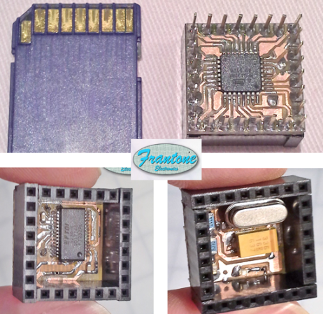
[Fran's] been working on her own version of the Arduino. She calls it CuteUino for obvious reasons. The size of the thing is pretty remarkable, fitting within the outline of an SD card. But that doesn’t mean you won’t get the power that you’re used to with the device. She’s broken it up into several modules so you can choose only the components that you need for the project.

The main board is shown on the right, both top and bottom. It sports the ATmega328p (it’s hard to believe we could make out the label on the chip package in the clip after the break) in a TQFP-32 package soldered to the underside of what she calls the Brain Module. You can also see the extra long pins which stick through from the female pin headers mounted on the top side of the board. Inside of these pin headers you’ll find the clock crystal, status LEDs, and a capacitor. The other module is an FTDI board used to connect the AVR chip to a USB port.

You’ll definitely want to check out her prototyping post for this project. She uses a very interesting technique of combining two single-sided boards to make a 3-layer PCB. The side that was not copper clad is fitted with copper foil by hand to act as a ground plane for the vias. Neat!

[Read more...]